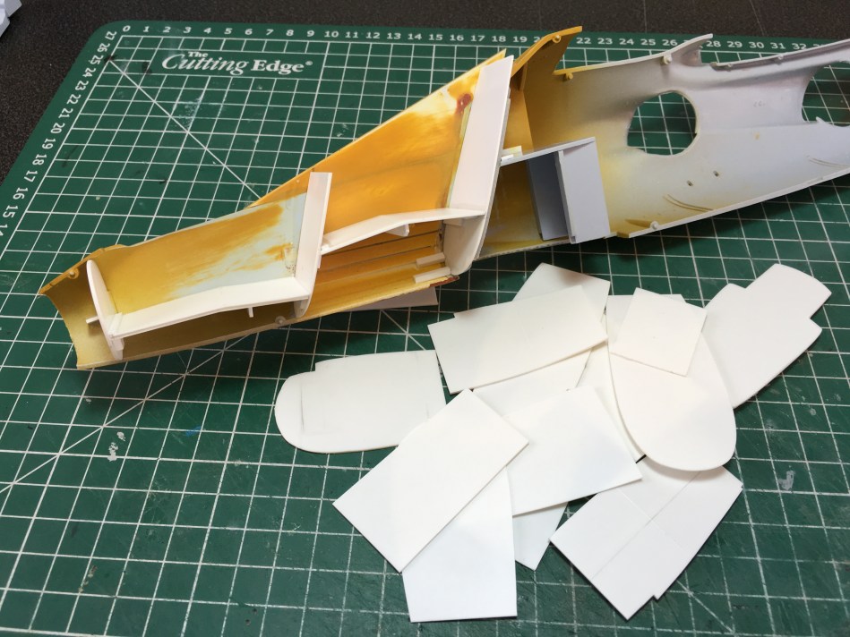
As you can see from the images that accompany this update, I cut out a whole heap of parts before finally creating ones that fit correctly – and even now, they are not quite perfect, but they are close
Having completed the extension of the nose and left it to dry out, I gave it another coat of filler primer and set it aside for a week to set. It was tempting to start sanding once more, but I decided to leave well alone until the cockpit is completely built and painted – maybe then, the damned ghost seams will have disappeared!
So, today, with that step out of the way, I decided to tackle the basic cockpit structure. In a recent Harrier video on my YouTube channel – https://www.youtube.com/watch?v=AfQeFAMdUVY – I discussed the basic ideas behind the construction of the floor, bulkheads and other structural members and how some had already been dealt with. Taking another look today, I was not so sure that the results were what I wanted, so went back to the drawing board – well, to a point.
During the extension of the nose I’d used strips of Evergreen to strengthen the plug and these strips had fouled the interior. Initially, I’d cut slots in the bulkheads to clear these strips, electing to bodge some detail to cover the compromise in construction. Looking again, I felt that this was unacceptable, so milled the offending parts away using a dental burr mounted in a mini-drill, finishing off the scruffy surfaces with sanding sticks and sand paper. Once done, new bulkheads could be fashioned from 1 mm plasticard using the old pieces as a template, care being taken to ensure they were identical to those already fabricated. This was easier said than done as it turned out; constant adjustment and repeated attempts were needed until I was happy with the results, but after a few hours, the bulkheads were ready to be fixed in place.
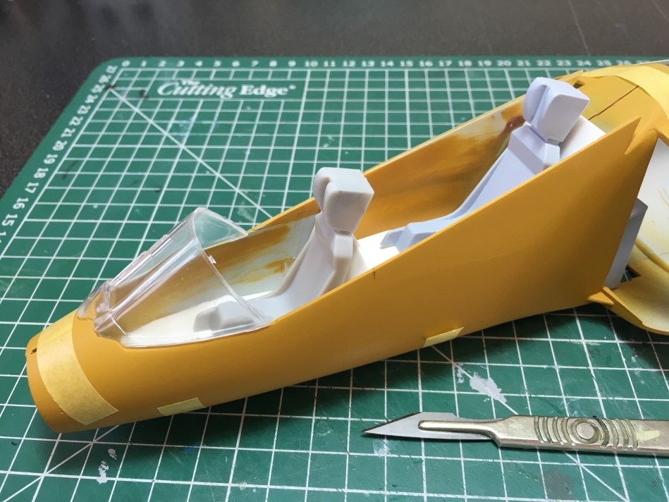
With the vertical structures done, the tricky task of dealing with the floors could be faced head-on. This was something that had given me sleepless nights, so I knew that there would be no easy way of dealing with them, other than measurement, cutting and sanding, until the parts fit. Creating pieces that were the right length was easy, a set of Tamiya callipers being used to measure inside the nose, before transferring the dimensions to some more 1 mm plasticard. The same tool was also used to gauge their width, before using the Airfix tub to ascertain the correct shape of the floor and the angle of the kink that can be found midway along its length. It was just a case of adjusting the edges until they fit the inner shape of the nose. That sounds easy, eh? It was not. I spent several hours on two plasticard plates little more than 5 cm x 2 cm, carefully adjusting their edges until they were the right shape – a tedious, mind-numbing process, but one that was extremely important to the look of the finished cockpit.
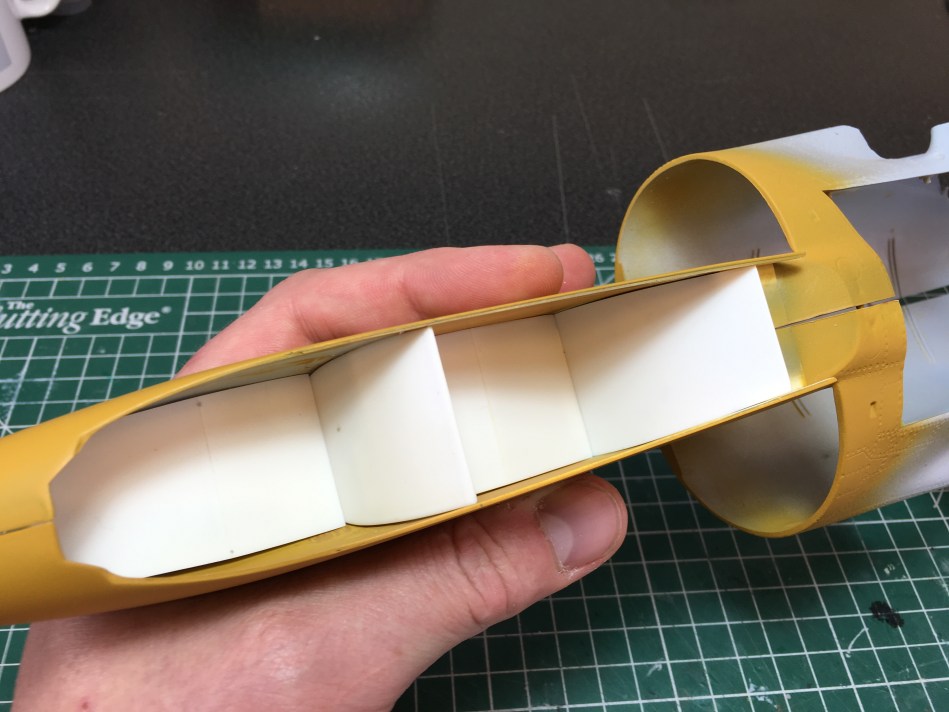
As you can see from the images that accompany this update, I cut out a whole heap of parts before finally creating ones that fit correctly – and even now, they are not quite perfect, but they are close. Once happy, that the parts fit neatly, they were glued together and then secured to the starboard fuselage half. As discussed in the video, this was an insurance policy against inaccurate placement and the space and size of the model is such that access to add further detail and then paint the results, is far from restricted. Initially, the parts were cemented in place with Gunze Sangyo Mr Cement R and then left to dry. Once happy, that the joints were secure, they were further reinforced with small lengths of Evergreen strip, differently sized pieces being used to anchor everything firmly in place. This was particularly important around the kit’s nose wheel bay, the fit being less than perfect and thus the union between the bay and the inner nose, being far from secure! With the blocks in place though the who shooting match became solid and more secure, the internal structure also helping to stiffen up the extended nose and stop it flexing as much as it did whilst still empty.

Completing this part of the build was greeted with a sigh of relief. I’d spent a long time wondering just how I would go about building these structures and so now being able to see them in place, is certainly pleasing! The next step is to start building the internal structures, ribs, stringers, consoles and instrument panels, before adding all of the smaller features. There’s a long way to go, but at least I’m now starting to make progress…

0 comments on “HARRIER T.4 CONVERSION – PART 3”